SMΩRF RF Vector Signal Meter
Out of stock
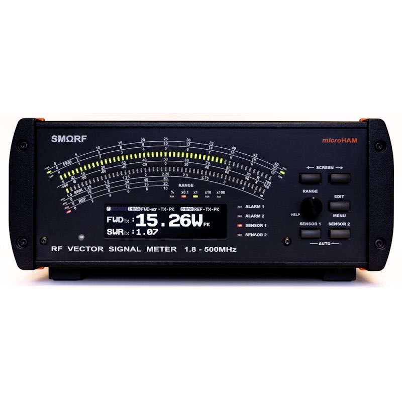
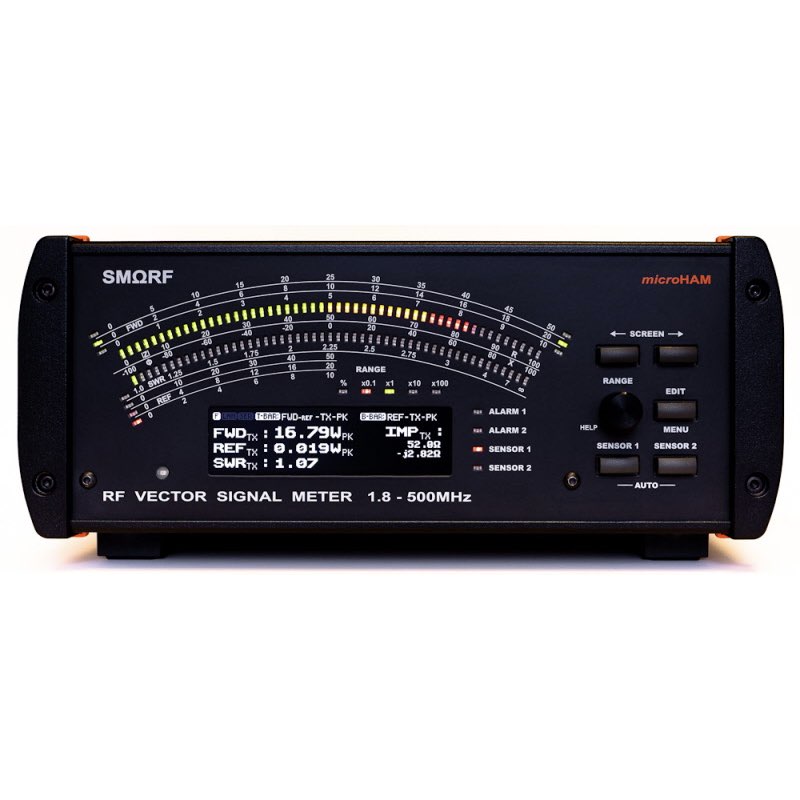
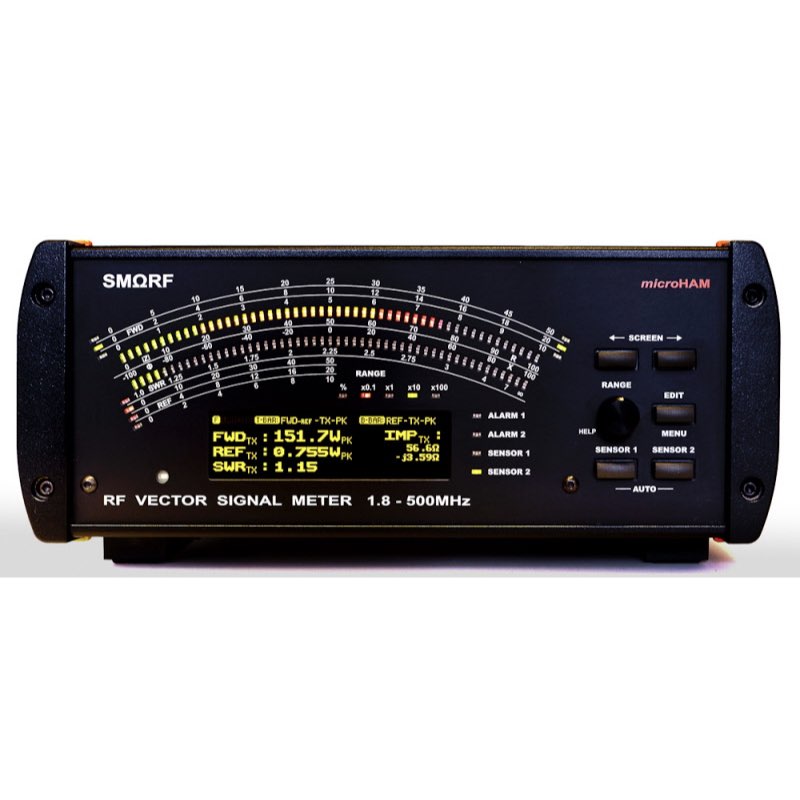
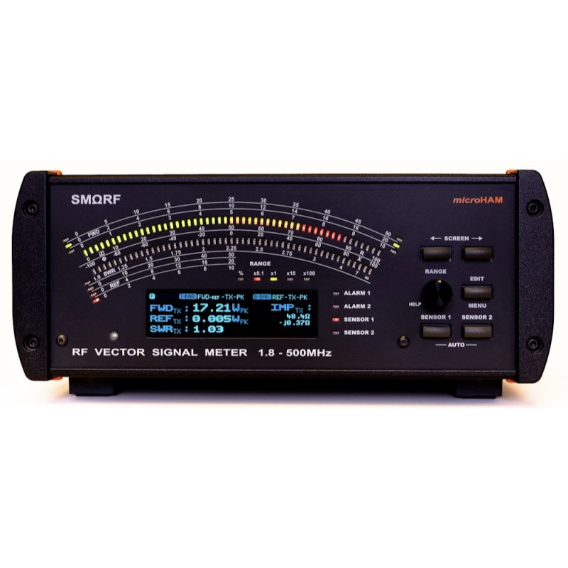
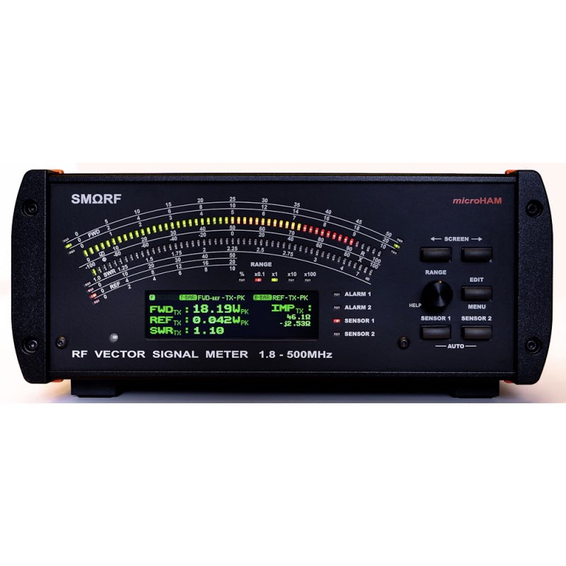
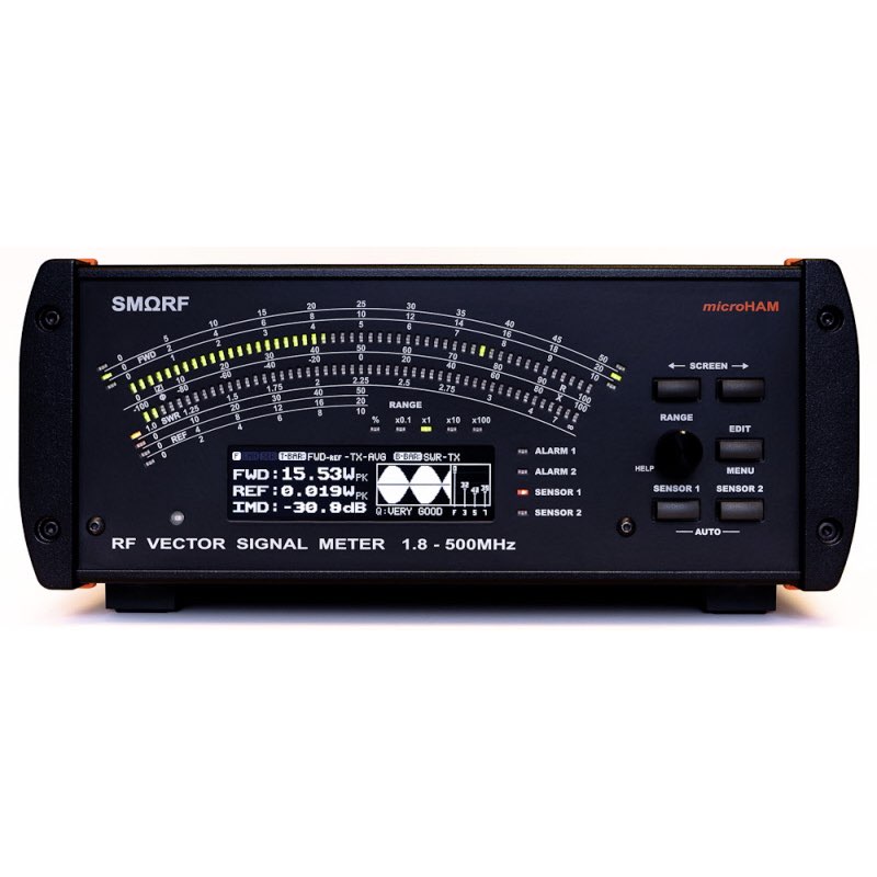
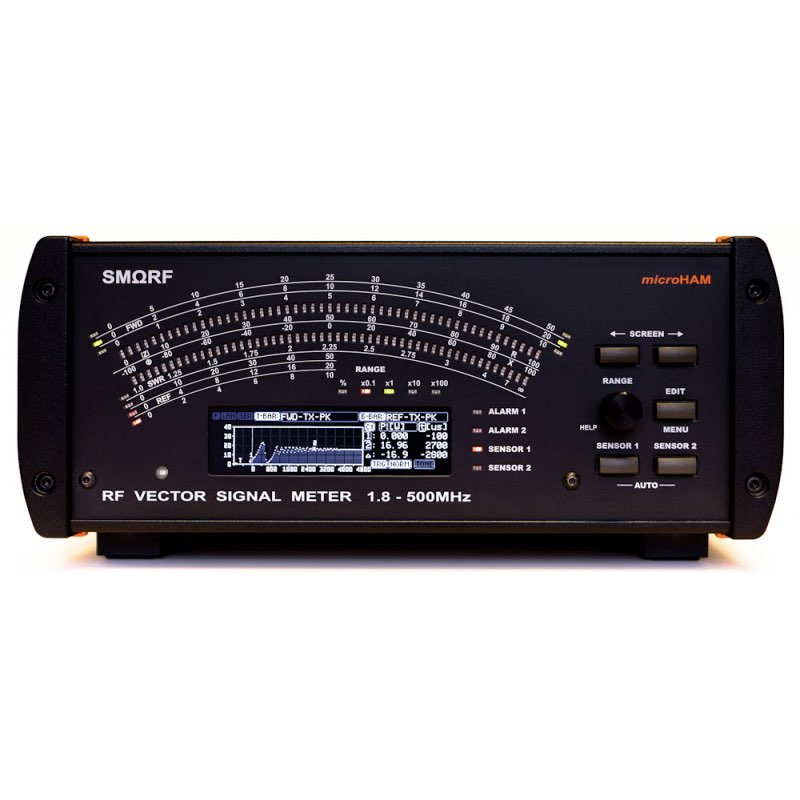
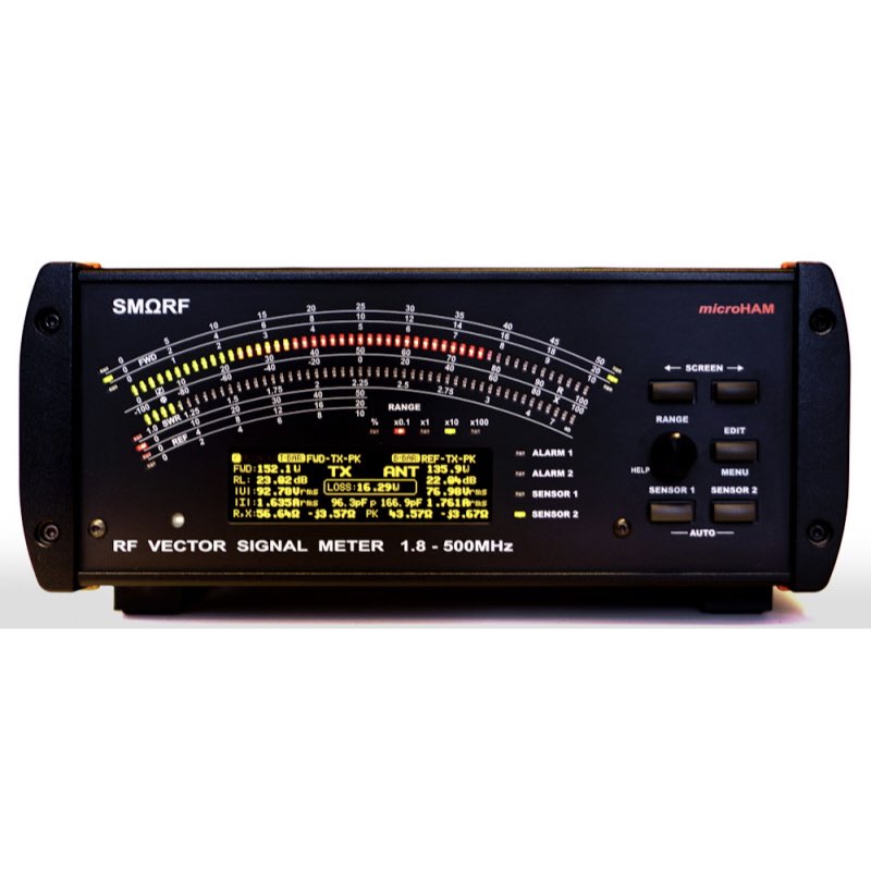
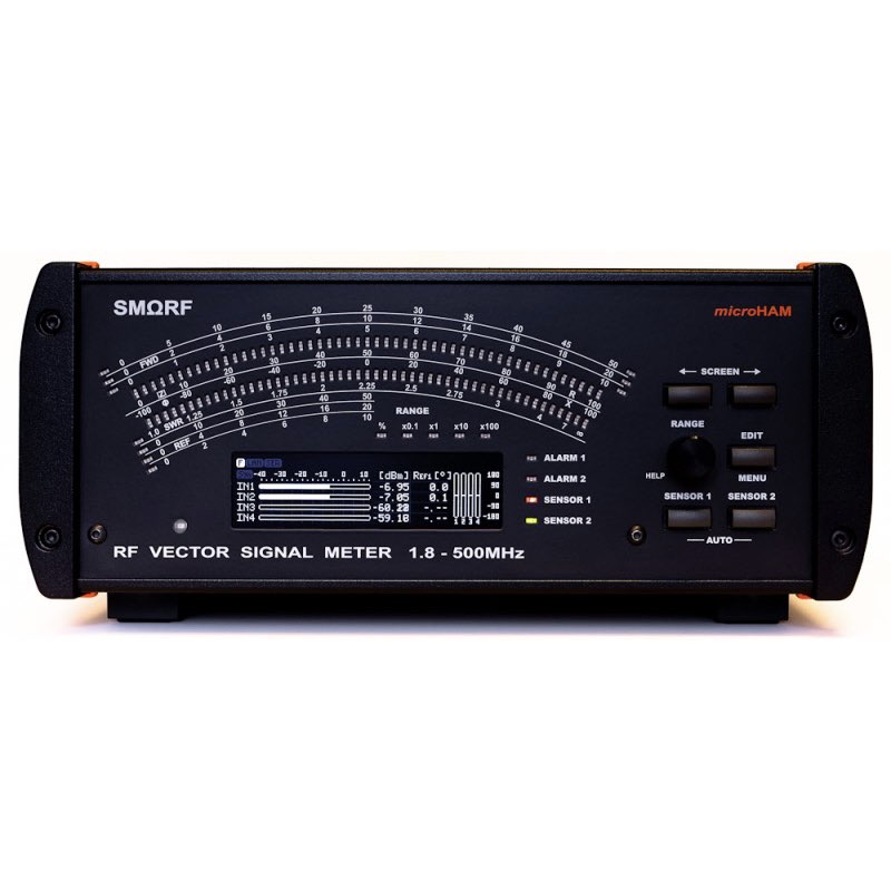
SMΩRF™ RF Vector Power Meter for measuring all kinds of Power, SWR, Impedance, Phase and Transmission Lines with built-in audio signal generator, oscilloscope and Internet connectivity. SMΩRF™ from microHAMis the most powerful and accurate, in-line RF Vector Signal Meter to date with accuracy rivalling professional instruments.
Power sensors ordered separately.
The SMΩRF™ RF Vector Power Meter has been discontinued. We recommend the MetroPWR range of Vector Power Meters.
1,094.90 $
Out of stock
SMΩRF™ connects to the power RF signal by remote sensor, available in several models for power levels up to 12KW and frequencies from 1.8MHz up to 500MHz. The SMΩRF™ can simultaneously measure two independent signals from any two sensors and shows measurement results on its front panel or computer.
HF + 6m sensors are provided in three models for 3kW, 6kW (1.8-54MHz) and 12kW (1.8-30MHz) maximal peak power. VHF/UHF sensors (70-500MHz) are provided in two models for 2KW and 6KW maximal peak power.
Vector measurements (signed complex impedance measurement) are provided with all sensors.
SMΩRF™ is not only desktop instrument but Internet enabled device too. Using native IEEE 802.3 Ethernet port provides all measurement results directly to your remote computer, tablet or phone over LAN or the Internet. Does not require local computer. For remote connectivity provides free, open TCP protocol based, high speed Remote Control application for the Windows and macOS, as well as internal HTTP and VNC server for maintenance access from the web browser and VNC viewer (Windows, macOS, iOS, Linux, Android).
Every SMΩRF™ base unit, every Sensor, and every Sensor Cable connecting the sensor is individually calibrated on regularly calibrated laboratory instruments (ISO/IEC17025, NIST traceable) using specialized, temperature and computer controlled setup in our lab. The SMΩRF™ and the Sensor keep calibration data in their memory and every Sensor Cable is provided with the unique Calibration Certificate containing calibration table.
SMΩRF™ measures frequency and automatically applies all these calibration data in real-time to provide measurements with ultimate accuracy. Changing or adding new Sensor does not require any factory or user recalibration. In addition, the SMΩRF™ provides simple, built-in calibration process for custom sensor cables if supplied cables are not long enough for user’s application, without any requirement for external metering equipment. You are always at the best accuracy.
SMΩRF Features
Main features:
- Operating frequency from 1.8 – 500MHz.
- Signed phase metering up to 500MHz.
- Two points of measurement, at the sensor point and at the antenna point.
- Phase measurement between sensors.*
- Real time temperature compensation in the meter and the sensor.
- Every meter and every sensor individually calibrated for the best accuracy. Temperature controlled, computer automatized calibration setup makes over 10,000 calibration points in each meter and over 100 points in each sensor. Calibrated per port for level, frequency, phase, and temperature.
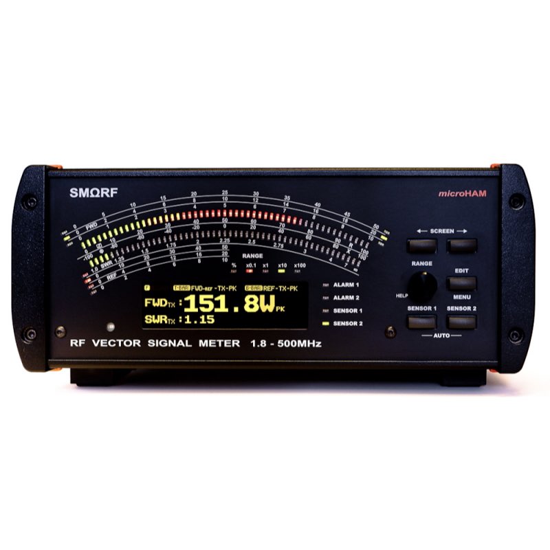
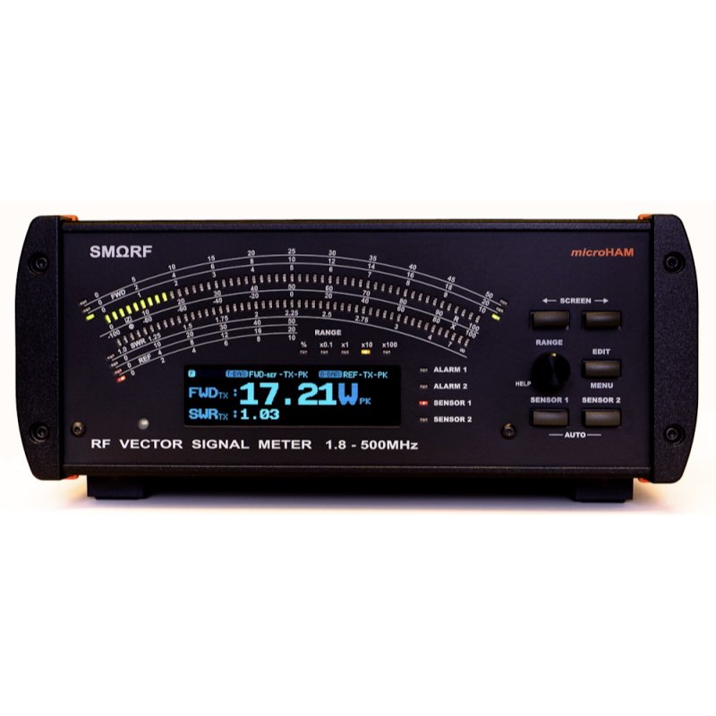
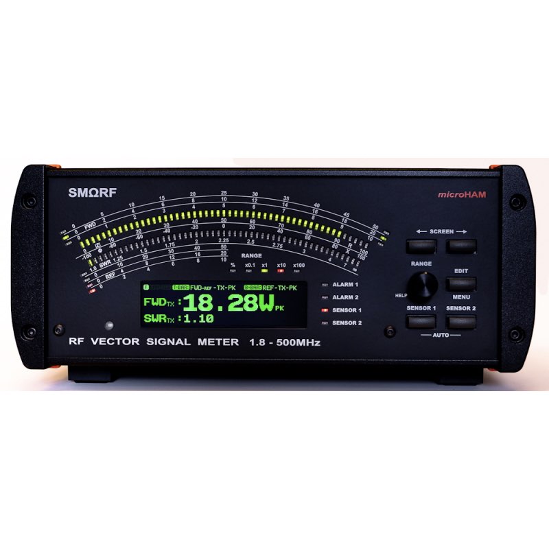
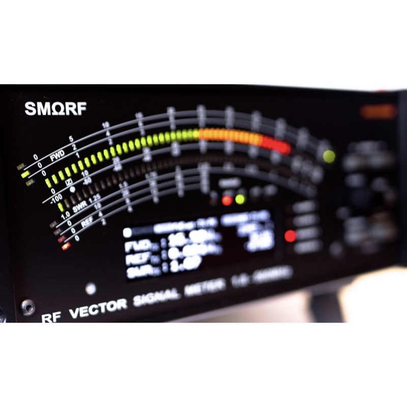
- Dual, high speed, three color, user adjustable auto-ranging LED bar graphs with configurable peak hold.
- Very wide viewing angle, sunlight readable, high contrast graphics OLED display.
- Multiple, user configurable display screens for powers, impedances, waveform, spectrum, IMD …
- Single and Dual channel modes, auto mode for SO2R, special 4IN direct input mode.
- User configurable alarms (SWR, High Power, Low Power, PSK IMD, Arcing) in three stages (Warning, Alarm, Fault) for two power levels on per sensor, per band basis.
Connectivity:
- Internet enabled, native IEEE 802.3 Ethernet port for remote connectivity, no computer required.
- Internal HTTP server for seamless access from the computer browser for status checking, maintenance and firmware updates. No drivers, no specialized software installation.
- Internal VNC server for remote access to complete setup.
- Dedicated TCP port for high speed remote control applications, open protocol.
- Free Remote Control application provided for Windows and OS-X.
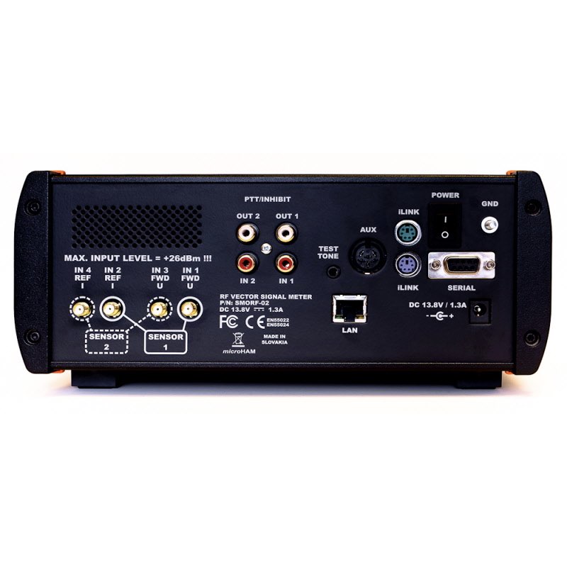
- Legacy RS232 port.
- High purity, DDS based test signal generator (single/dual tone, noise) for linearity and bandwidth tests.
- Two keying, configurable ports (2x IN, 2x OUT) for protections.
- iLINK port for simplified connectivity to our interfaces.
- Auxiliary port for future expansions (wall mount 7 segment LED displays, analog meter).
Other features:
- Internal speaker for audible warnings.
- Internet synchronized real time clock.
- Ambient light sensor for led bars and display brightness control.
- Fully EMI shielded, aluminum die cast enclosure.
Internal processing highlights:
- 210 MIPS, 32bit floating point Cortex M4 DSP processor for extremely fast updates and accurate calculation of complex functions.
- Hi-grade, parallel 16bit ADC, sampled at 125ksps.
- 24bit DAC at 160ksps for signal generator.
Package contains:
- SMΩRF™ RF Vector Signal Meter – one (1)
- iLINK cable (1.5m long) – one (1)
- Coaxial 2.1mm/5.5mm power plug – one (1)
- Four pole 3.5mm audio plug – one (1)
- Foster 8 female microphone plug – one (1)
- Printed Quick Start Guide – one (1)
Recommended accessories:
- CHF-6 – 6KW sensor 1.8MHz – 54MHz
- CHF-12 – 12KW sensor 1.8MHz – 30MHz
- CVHF-2 – 2 KW sensor 70MHz – 500 MHz
- CVHF-6 – 6 KW sensor 70MHz – 500 MHz
- Phased matched sensor cables 3m
- Phased matched sensor cables 10m
| Weight | 2.4 kg |
|---|---|
| Dimensions | 300 × 250 × 110 cm |
| Color | Blue, Green, Yellow, White |
Specifications
SMΩRF (Meter) CHARACTERISTIC
*1 Requires two sensors *2 Muxed inputs IN1-IN3, IN2-IN4
*3 Absolute accuracy to NIST traceable HP438A SN#2517U00290, HP8482A SN#2652A22248, HP8482A SN#1925A05693 for levels -20dBm to +23dBm, Keysight U2004A SN# MY53290005 for levels -60dBm to -20dBm
*4 RSS (Root Sum of Squares) uncertainty for complete system including sensor mismatch, sensor calibration, sensor cables, SMΩRF calibration and reference power meter uncertainties.


There are no reviews yet.